Links
- Schematic + wiring guide: github.com/IamMrCupp/pcie-gpu-test-rig (MIT)
- Printed enclosure: 3d-printer-models → pcie-rig-enclosure
- Write-up: A Power Box for Dead GPUs
About
The first diagnostic step for every graphics card on the bench: power it through a PCIe riser and its aux connectors from a current-limited supply, with no motherboard, and read the current. Nothing means the rails aren’t coming up, 1–2.5 A means it’s idling, and a short drags the supply into current limit instead of taking anything with it.
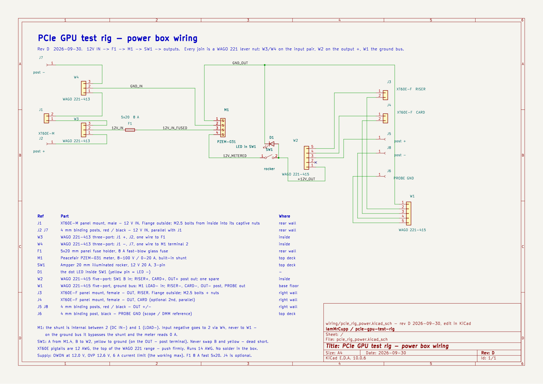
12 V in → 8 A fuse → PZEM-031 meter → rocker → outputs, with keyed XT60 outputs for the riser and the card, banana pairs for probing, and a probe-ground post on the card’s return bus. The bench supply is the protection — 12.0 V, OVP 12.6 V, 6 A limit. Never an ATX or server supply.
Rev D, the current one, makes every join inside a WAGO lever nut — no solder, and no terminal with two wires on it.
Parts
Some links are affiliate links — no extra cost to you, a little back to the bench.
| Part | Notes |
|---|---|
| Peacefair PZEM-031 meter | 8–100 V / 0–20 A, built-in shunt in the negative leg |
| Ampper 20 mm illuminated rocker | 12 V 20 A, 3-pin — beep load vs LED before crimping |
| 5×20 panel fuse holder kit | 8 A fast-blow; the kit steps 5 → 8, and 5 blows in normal use |
| 4 mm binding posts | inputs, outputs, and the probe-ground post |
| Kingwin PCIe x1 → x16 riser kit | only the x16 slot board is used |
| XT60E-M / XT60E-F panel connectors | keyed input and outputs |
| WAGO 221-413 lever nuts (×2) | the input pair |
| WAGO 221-415 lever nuts (×2) | the switched + bus and the ground bus |
| 14 AWG silicone wire, spades, ferrules | 14 AWG on every 12 V and ground run |
The full parts list is in BOM.md, the build procedure, continuity table, and first power-up in BUILD.md, and the wire-by-wire reference in WIRING.md.